Constrain sketch geometry
Sketch constraints relate selected entities while you edit a sketch. This guide shows Parallel, Perpendicular, Tangent, Equal length, Angle, Symmetry, and Radius / Diameter constraints.
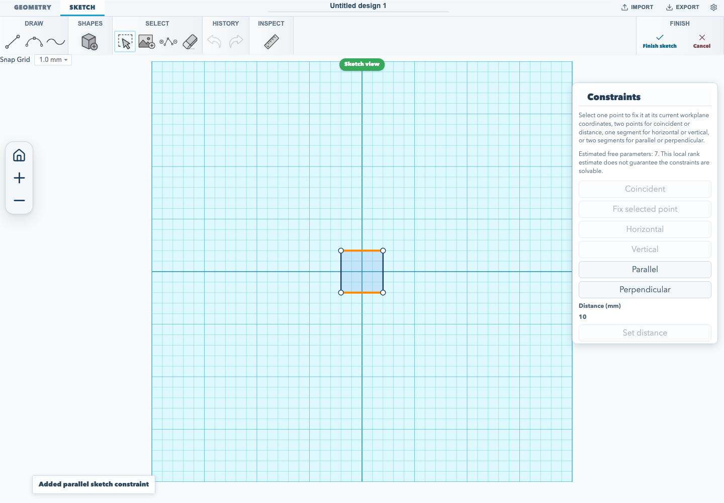
Make two segments parallel
- Create a sketch with at least two line segments, or edit a rectangular sketch.
- Select the two segments. For the rectangle, drag a selection marquee over the two opposite vertical sides.
- Choose Parallel in the sketch constraint toolbar.
The constraint aligns the segments' directions. It does not move the segments to the same line or change their offset, so the opposite sides stay separated. The workflow below checks that the two segments are selected, applies the constraint, and confirms the resulting constraint in the editor.
Make two segments perpendicular
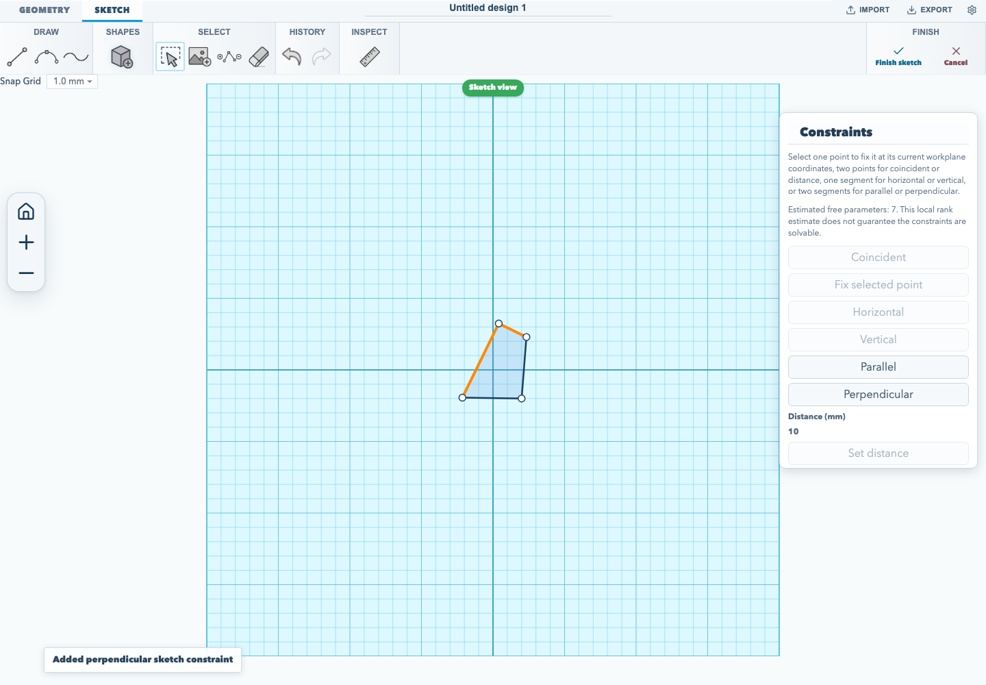
- Create a rectangular sketch and choose Edit sketch.
- Drag one corner so the two adjoining sides no longer meet at 90 degrees.
- Drag a selection marquee around the midpoints of those two adjoining sides.
- Choose Perpendicular in the sketch constraint toolbar.
The constraint solver adjusts the selected segments until they meet at 90 degrees. The browser acceptance flow checks the initial angle, applies the relation, and measures the resulting angle before capturing the editor state.
Make two segments equal in length
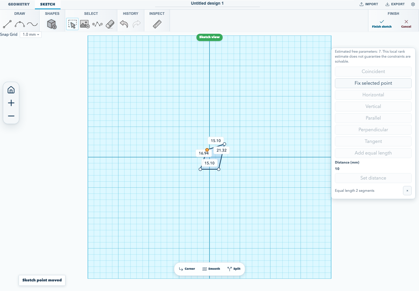
- Create a sketch with two non-zero-length line segments.
- Select both line segments.
- Choose Equal length in the sketch constraint toolbar.
The solver adjusts the segments so their lengths match while preserving any anchored point. This relation removes one estimated degree of freedom and is stored in .skf projects. Curves and zero-length lines are not eligible.
Set the angle between two segments
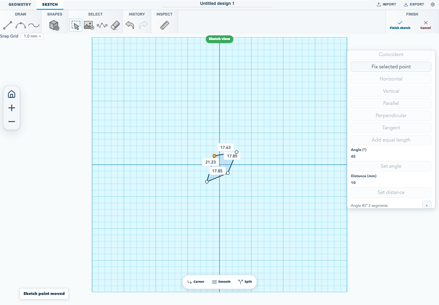
- Create a sketch with two non-zero-length segments.
- Select both segments.
- Enter the angle in degrees and choose Set angle.
The solver turns the second segment around the anchored geometry until the unsigned angle between the two segments matches the value. The angle is measured from 0° to 180°, so 90° is the same relation as Perpendicular; use whichever name fits the design. The relation removes one estimated degree of freedom and is stored in .skf projects. A zero-length segment is refused, and the angle must stay between 0° and 180°.
Make two points symmetric about a line
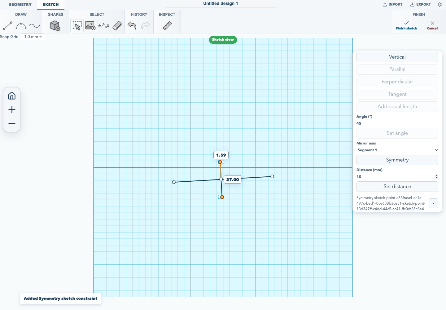
- Draw the line you want to use as the mirror axis, then draw or place the two points that should mirror across it.
- Select the two points. Choose the axis in the Mirror axis list — the first non-zero-length segment is selected by default.
- Choose Symmetry.
The solver puts the points' midpoint on the axis and turns the line between them perpendicular to the axis, so the two points end up the same distance from it on opposite sides. The relation removes two estimated degrees of freedom and is stored in .skf projects. A zero-length axis or two identical points are refused.
Set a radius or diameter
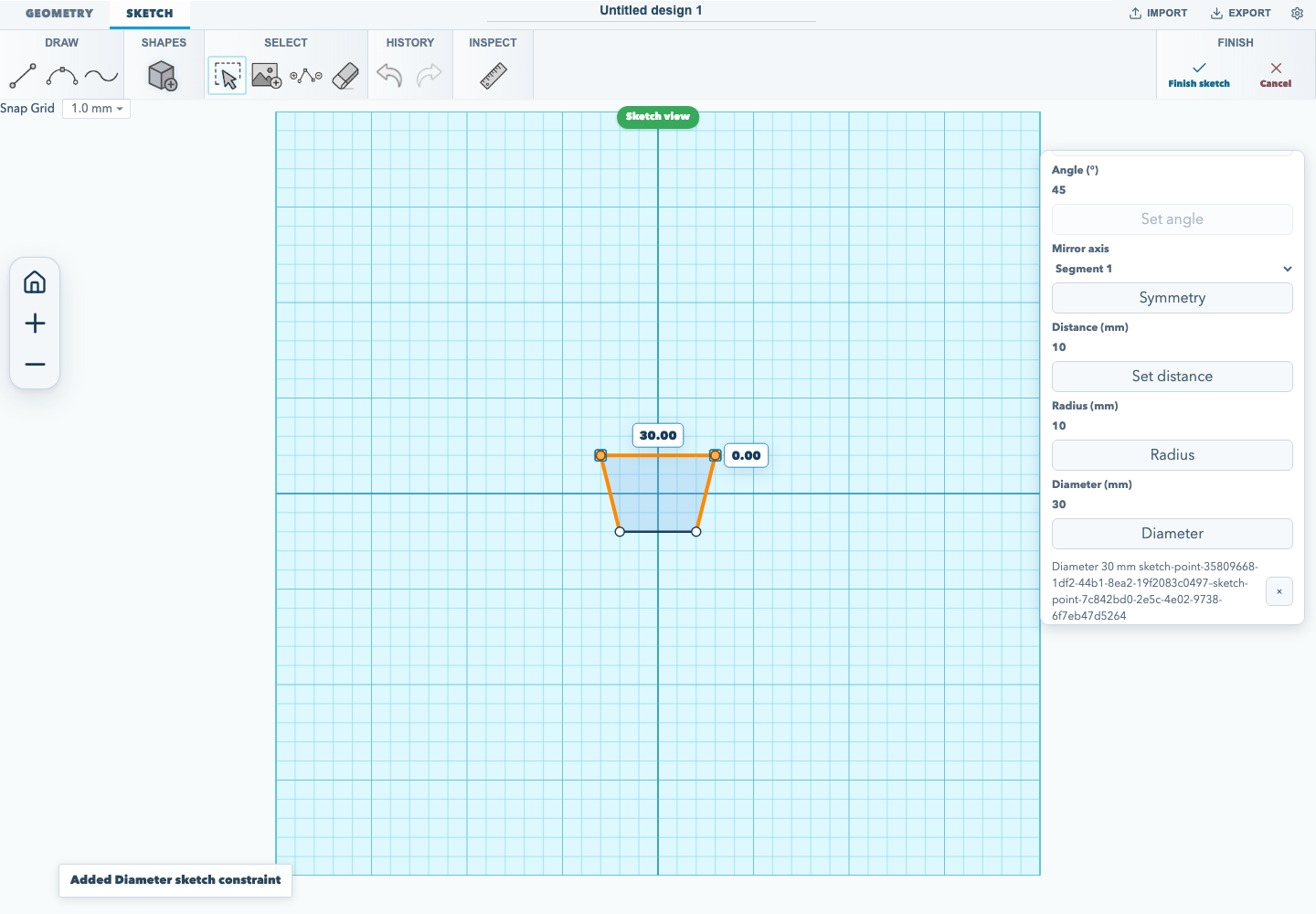
- Select two points that sit at opposite ends of the diameter. For a circle primitive, drag a narrow selection band through the centre so only one pair of opposite rim points is selected.
- Enter the Radius (mm) or Diameter (mm) value.
- Choose Radius or Diameter.
Radius keeps the distance between the two points at twice the entered value; Diameter keeps it at the entered value. The relation removes one estimated degree of freedom and is stored in .skf projects. The two points must be different and the value must be greater than zero. For a circle, use Diameter on two opposite rim points to set its size directly.
Make a line tangent to a Bezier
- Draw a line and a Bezier segment that meet at one endpoint. Give the Bezier endpoint a control handle.
- Select the line and Bezier segment together.
- Choose Tangent in the sketch constraint toolbar.
The solver keeps the line direction aligned with the Bezier's endpoint handle while the shared point moves. The relation removes one estimated degree of freedom. The segments must share exactly one endpoint; tangent constraints between unsupported segment types are refused when a .skf project is read.
Run the browser acceptance flow with:
npm run test:browserFor the full create-and-export walkthrough, see make and export your first model. For constraints on solid faces, see the face-drafting guide.
Documentation version: 1.30.0 · Repository revision: 1cb9fee8dff4d394684c229dd67a21da539d167f · View source