Create, edit, save, and export a model
This workflow makes a block, adds a circular feature through sketch editing, confirms the project survives a reload, and exports an editable .skf project. It uses the editor's visible controls and default 10 mm extrusion height.
1. Create a project and the first solid
From the dashboard, choose Create new 3D design. In the editor, choose Sketch, then Sketch to 3D and Extrude sketch. Choose Add sketch shape and Rectangle, then Finish sketch. The rectangle becomes a solid named Sketch extrusion.
For the first model from a rectangle, see the editor quick start.
2. Edit the sketch to add a circular feature
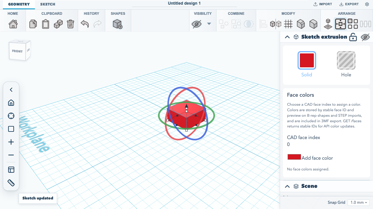
Select Sketch extrusion in the scene list and choose Edit sketch in the inspector. In sketch mode, choose Add sketch shape, then Circle. The circle is centered on the sketch origin, inside the rectangle. It adds a second closed profile to the sketch. Choose Finish sketch. The editor rebuilds the existing solid from the updated profile and reports Sketch updated.
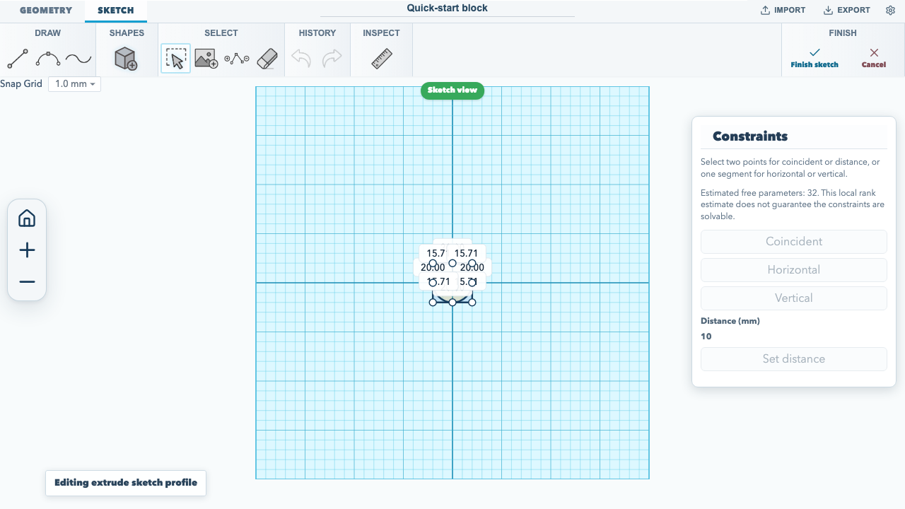
The editor retains the sketch profile as part of the extrusion. For a guided first sketch and an overview of the editor controls, see the editor quick start.
3. Save and confirm the edit
Rename the project in the field at the top of the editor and press Enter. Project changes save automatically in this browser. Reload the editor page while the project is open; confirm that Sketch extrusion and the project name remain. Browser storage is local to this browser profile.
4. Export a portable editable project
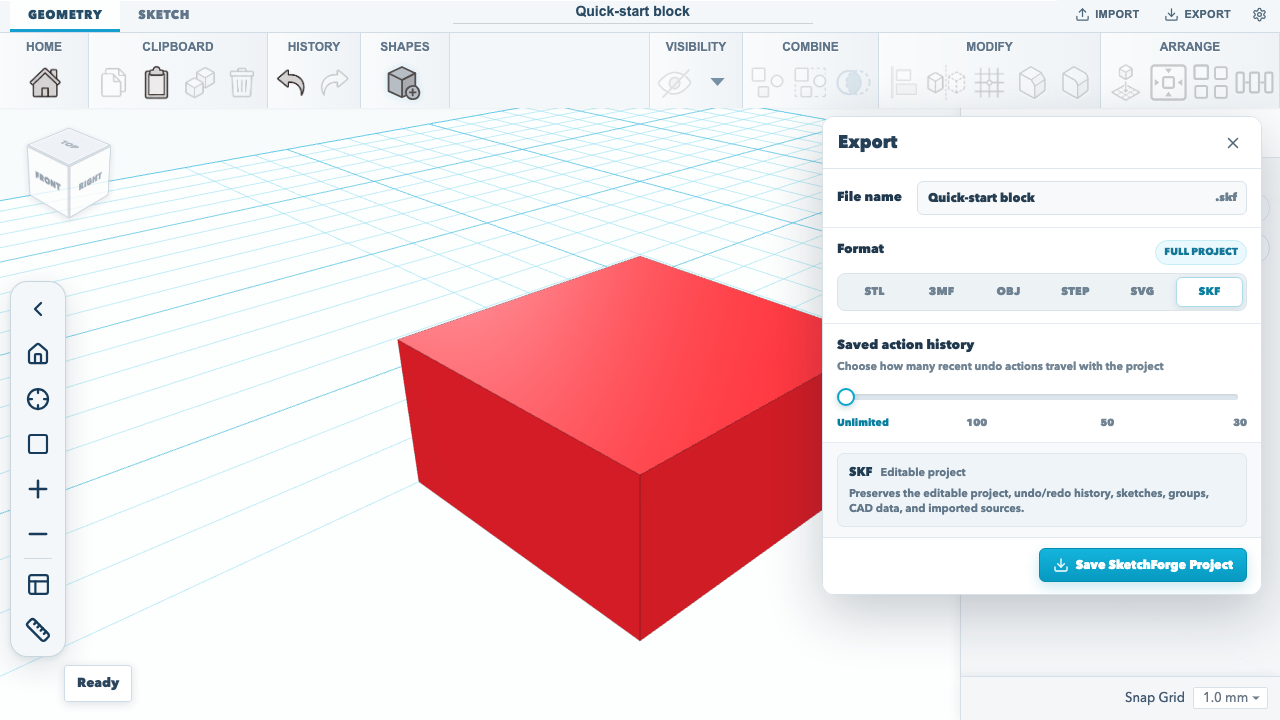
Choose Export, select SKF: Editable project, then choose Save SketchForge Project. The browser downloads a .skf file that preserves the editable sketch and project data. See the project format guide for more about what .skf stores and the editor quick start for other available mesh and CAD export formats.
5. Measure geometry and export a technical drawing
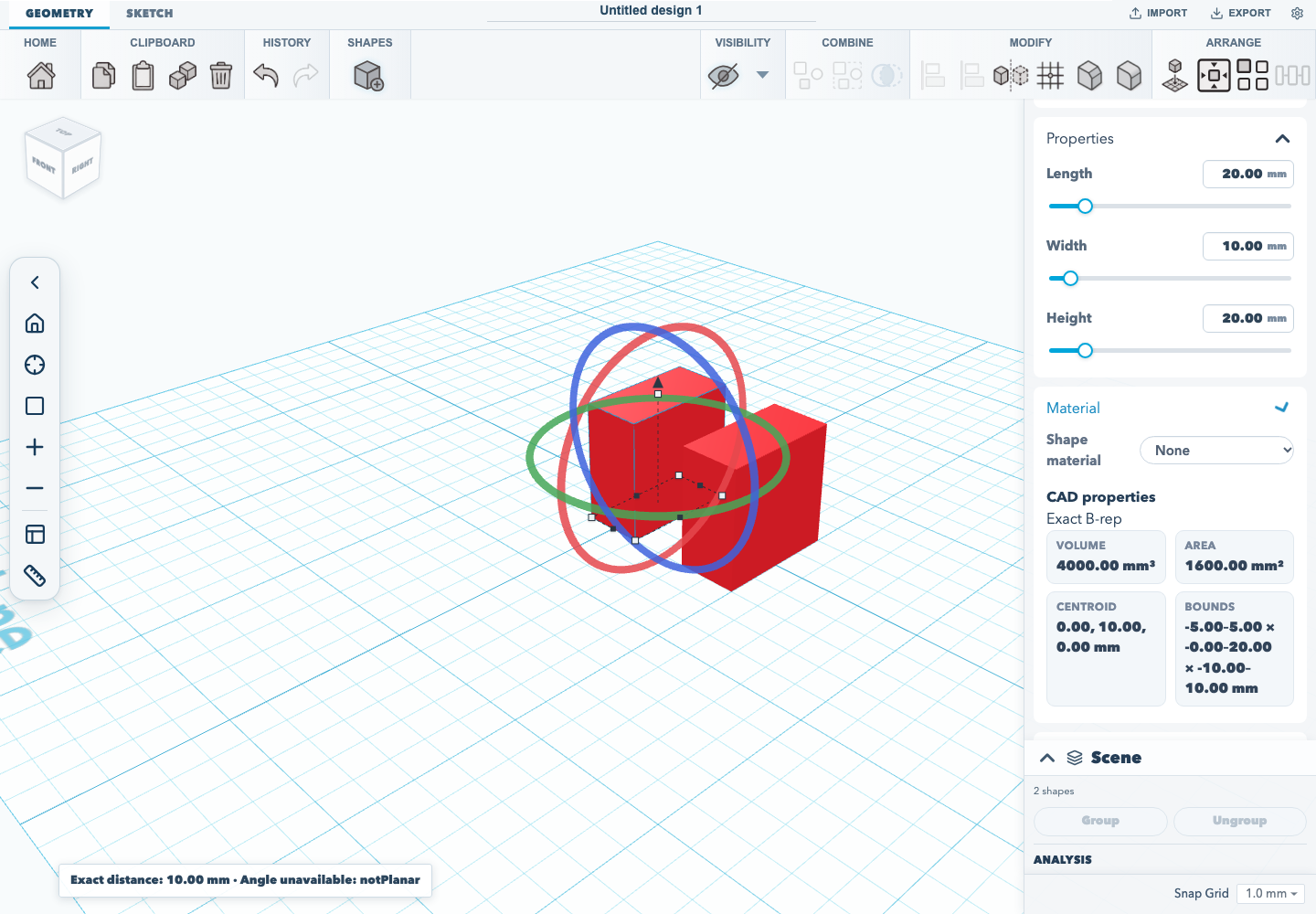
Select two shapes in the scene list, then choose Measure selected shapes. The measurement panel can compare the whole shapes or a face or edge index on each one. It reports exact minimum distance and, for two planar faces, their angle. An unavailable angle includes the kernel's reason. The inspector shows volume, area, centroid and bounds; imported meshes are labeled tessellated.
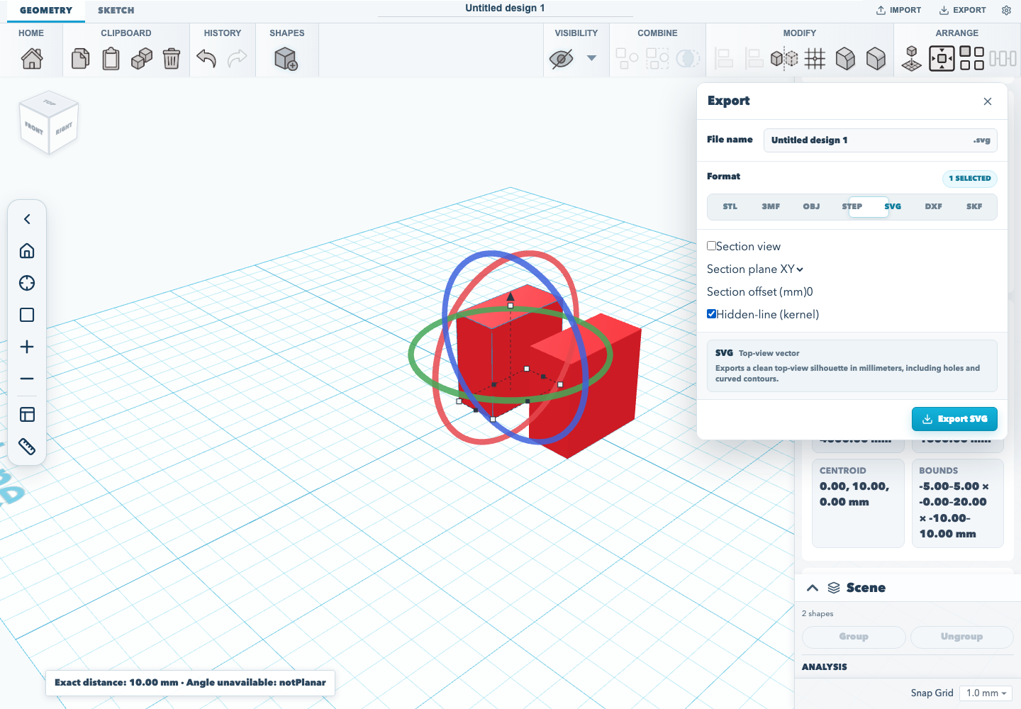
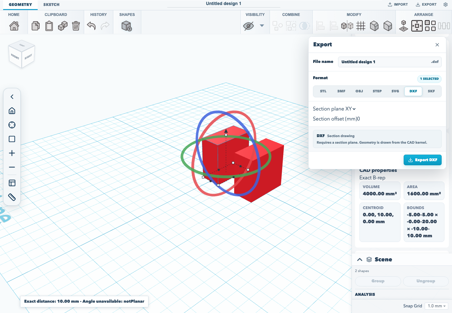
Choose Export, then select DXF and set the section plane and offset to export a kernel section drawing. For SVG, enable Hidden-line (kernel) for an exact projected drawing, or enable Section view for a section SVG. DXF always requires a section plane.
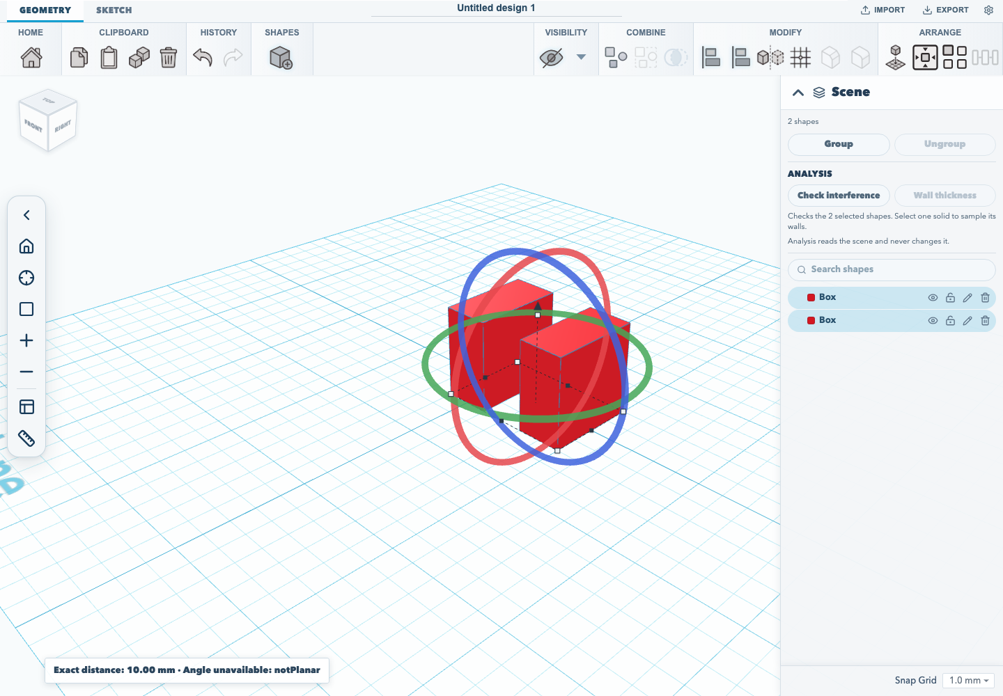
The inspector distinguishes exact B-rep values from measurements derived from an imported mesh.
Verified workflow
The browser acceptance test performs these steps: it creates the rectangular extrusion, opens Edit sketch, adds the circle, finishes the edit, renames and reloads the project, reopens the sketch to confirm the added segments persisted, then downloads the .skf file. Run it with:
npm run test:browserDocumentation version: 1.30.0 · Repository revision: 1cb9fee8dff4d394684c229dd67a21da539d167f · View source